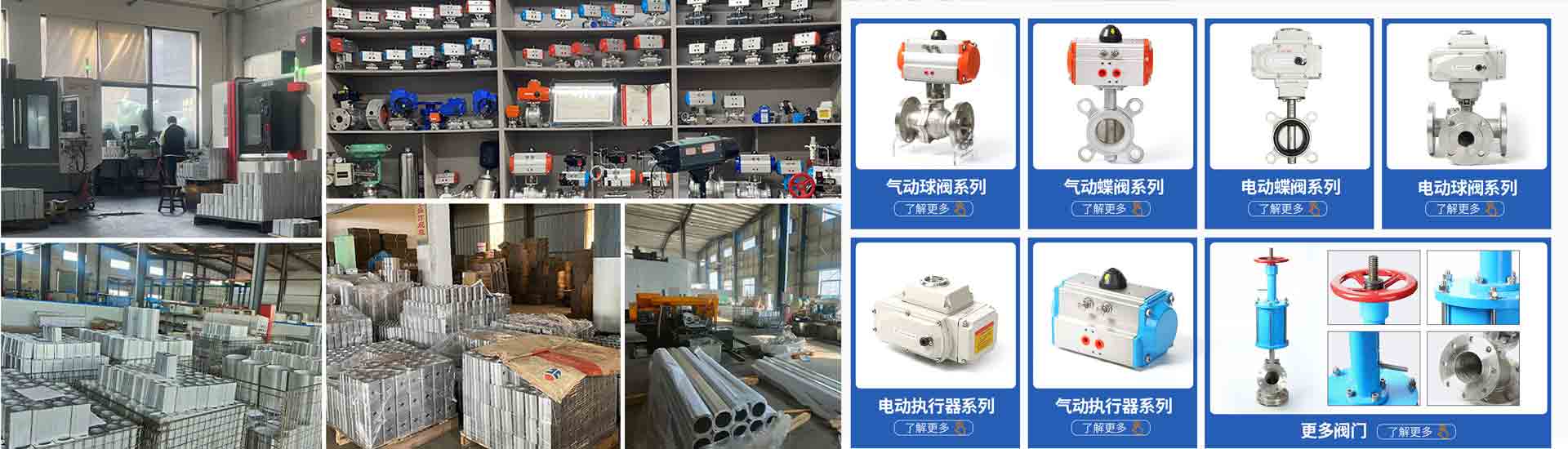
1、 Overview of pneumatic actuators
Pneumatic actuator is an actuating device that uses pneumatic pressure to drive the opening, closing or regulating of valves, also known as pneumatic actuator or pneumatic device, but generally referred to as pneumatic head. The actuator and regulating mechanism of pneumatic actuators are a unified whole, and their actuators include diaphragm type, piston type, fork type, and gear rack type.
Piston type with long stroke, suitable for situations requiring high thrust; The thin film type has a smaller stroke and can only directly drive the valve stem. Fork type pneumatic actuators have the characteristics of high torque, small space, and torque curves that better match the torque curve of valves, but they are not very aesthetically pleasing; Commonly used on valves with high torque. Gear and rack pneumatic actuators have the advantages of simple structure, smooth and reliable action, and safety and explosion prevention. They are widely used in production processes with high safety requirements such as power plants, chemicals, and refineries.
2、 Working principle of pneumatic actuator
Comprehensive technical analysis of pneumatic actuators (Figure 1)
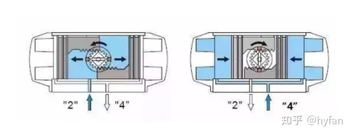
1. Working principle diagram of double acting pneumatic actuator
When the air source pressure enters the middle chamber between the two pistons of the cylinder from the air port (2), the two pistons separate and move towards the two ends of the cylinder. The air in the two end chambers is discharged through the air port (4), and at the same time, the two piston racks synchronously drive the output shaft (gear) to rotate counterclockwise. On the contrary, when the air source pressure enters the air chambers at both ends of the cylinder from the air port (4), it causes the two pistons to move towards the middle of the cylinder, and the air in the middle chamber is discharged through the air port (2). At the same time, the two piston racks synchronously drive the output shaft (gear) to rotate clockwise. If the piston is installed in the opposite direction, the output shaft will rotate in the opposite direction
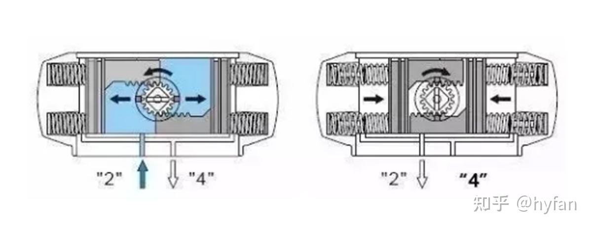
2. Working principle diagram of single acting pneumatic actuator
When the air source pressure enters the middle chamber between the two pistons of the cylinder from the air port (2), it causes the two pistons to separate and move towards the two ends of the cylinder, forcing the springs at both ends to compress. The air in the two end chambers is discharged through the air port (4), and at the same time, the two piston racks synchronously drive the output shaft (gear) to rotate counterclockwise. After the air source pressure passes through the solenoid valve, the two pistons of the cylinder move in the middle direction under the elastic force of the spring. The air in the middle chamber is discharged from the air port (2), and at the same time, the two piston racks synchronously drive the output shaft (gear) to rotate clockwise. If the piston is installed in the opposite direction, the output shaft will rotate in the opposite direction when the spring returns.
3、 Classification of pneumatic actuators
Comprehensive technical analysis of pneumatic actuators (Figure 3)
1. Thin film actuator
Thin film actuators are commonly used as pushing devices for general control valves, forming pneumatic thin film actuators. The signal pressure p of the pneumatic diaphragm actuator acts on the diaphragm, causing it to deform and driving the push rod on the diaphragm to move, causing displacement of the valve core and changing the valve opening. It has a simple structure, low price, easy maintenance, and wide application.
Pneumatic thin film actuators have two forms of positive and negative effects.
When the signal pressure from the controller or valve positioner increases, the downward movement of the valve stem is called a positive action actuator; When the signal pressure increases, the upward movement of the valve stem is called a reaction actuator. The signal pressure of the positive actuator is transmitted into the thin film chamber above the corrugated membrane; The signal pressure of the reaction actuator is transmitted into the thin film chamber below the corrugated membrane. By replacing individual parts, the two can be retrofitted to each other.
2. Piston type actuator
The pneumatic piston actuator moves the piston in the cylinder to generate thrust, and obviously, the output force of the piston type is much greater than that of the diaphragm type. Therefore, the thin film type is suitable for situations with low output and high accuracy; Piston type is suitable for applications with high output force, such as large-diameter, high-pressure drop control, or butterfly valve propulsion devices. In addition to membrane and piston types, there is also a type of long stroke actuator that has a long stroke and high torque, suitable for outputting angular displacement and large torque.
The signal standard received by the pneumatic actuator is 0.02 to 0.1 MPa.
The main components of pneumatic piston actuators are cylinders, pistons, and push rods. The piston inside the cylinder moves with the change of pressure difference on both sides of the cylinder. According to their characteristics, they are divided into two types: proportional and two-dimensional. The two position system pushes the piston from the high-pressure side to the low-pressure side based on the magnitude of the operating pressure on both sides of the input piston. Proportional type is a valve positioner added on the basis of the two position type, which makes the displacement of the push rod proportional to the signal pressure.
3. Gear rack actuator
Gear and rack type (double piston and rack type) pneumatic actuators have the characteristics of compact structure, beautiful appearance, fast response, stable operation, and long service life. All accessories adopt advanced anti-corrosion treatment technology, which can adapt to various harsh working conditions. Its high and low temperature, as well as various special stroke actuators, have shown good performance in various application fields.
4、 Selection of pneumatic actuators
Before selecting a pneumatic actuator, please confirm the valve torque. And increase the safety value in torque, with water vapor or non lubricating liquid media increasing the safety value by 25%; Non lubricating slurry liquid medium increases the safety value by 30%.
When selecting a valve torque of 210NM, a gas source pressure of only 5bar, and a non lubricating steam medium, considering safety factors, increase the safety value by 25% to 262NM. Use the double acting output torque table to find the corresponding torque value when the gas source pressure is 5bar. 277NM, model POADA300, should be selected.
Comprehensive technical analysis of pneumatic actuators (Figure 4)
5、 Performance characteristics of pneumatic actuators
1. The rated output force or torque of the pneumatic device should comply with the provisions of GB/T12222 and GB/T12223, which are thin film actuators;
2. Under no-load conditions, input the specified air pressure into the cylinder, and its action should be smooth, without any jamming or crawling phenomenon;
Under an air pressure of 0.6 MPa, the output torque or thrust of the pneumatic device in both directions of opening and closing should not be less than the value indicated on the pneumatic device label, and the action should be flexible, without any deformation or other abnormal phenomena in any part;
When conducting sealing tests under high working pressure, the amount of air leaking from each side of the back pressure shall not exceed (3+0.15D) cm3/min (standard state); The amount of air leaking from the end cap and output shaft shall not exceed (3+0.15d) cm3/min;
5. The strength test shall be conducted at 1.5 times the maximum working pressure. After maintaining the test pressure for 3 minutes, there shall be no leakage or structural deformation in the cylinder body end cover and static sealing parts;
6. The number of times the pneumatic device simulates the action of a pneumatic valve, while maintaining the output torque or thrust capability in both directions, the number of opening and closing operations should not be less than 50000 times (one opening closing cycle);
7. Pneumatic devices with buffering mechanisms are not allowed to experience impact when the piston reaches the end of its stroke.